")
")
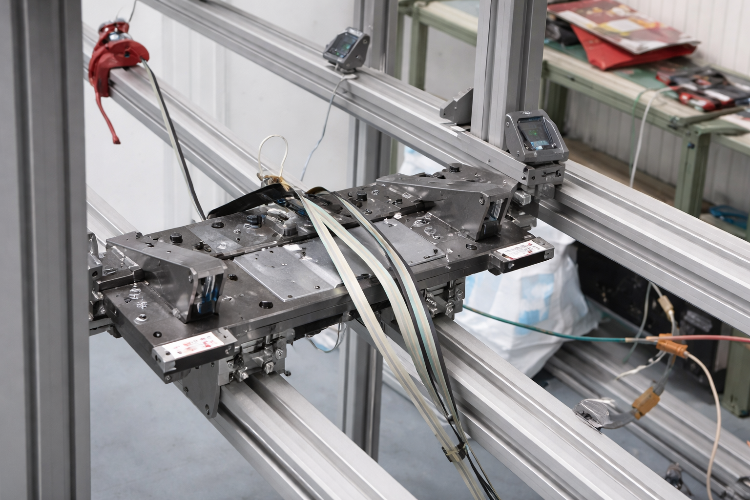
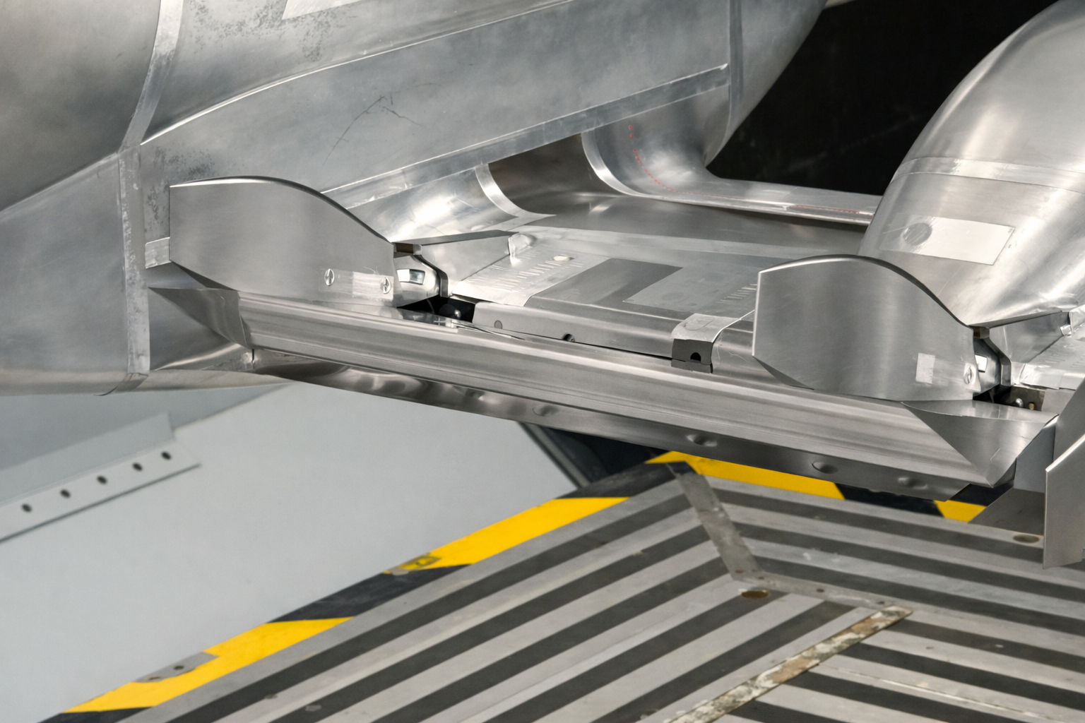
From concept to reality and into the wind tunnel.
Computer Aided Design of Wind Tunnel Models
Competence.
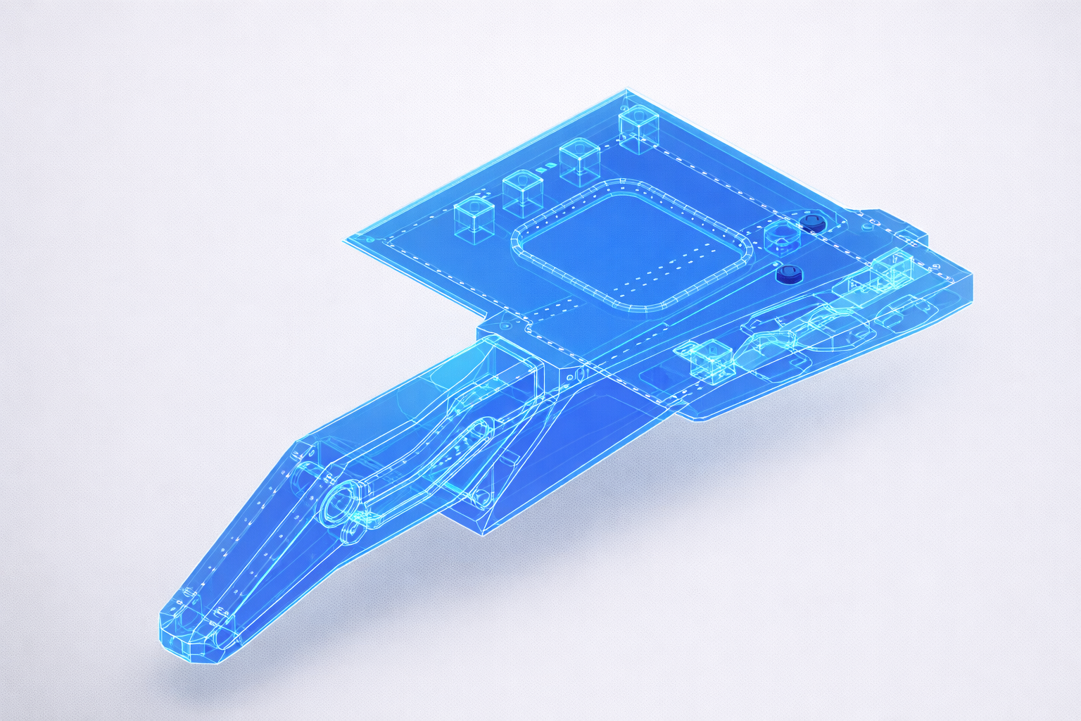
Mesh-ready geometry and test-ready hardware, including parametric bodies, modular inserts, balance interfaces, and disciplined surface management. Expect accurate data, rapid iterations, and clean handoffs to simulation and build.
Our Workflow
Concept Development and Requirements Analysis
Development and evaluation of technical concepts based on customer requirements in close collaboration with the client. Concepts are substantiated by engineering calculations, feasibility studies, and systematic assessments.
Component Research and Selection
Research, evaluation, and selection of purchased components in accordance with the technical, functional, and economic specifications defined during the concept phase.
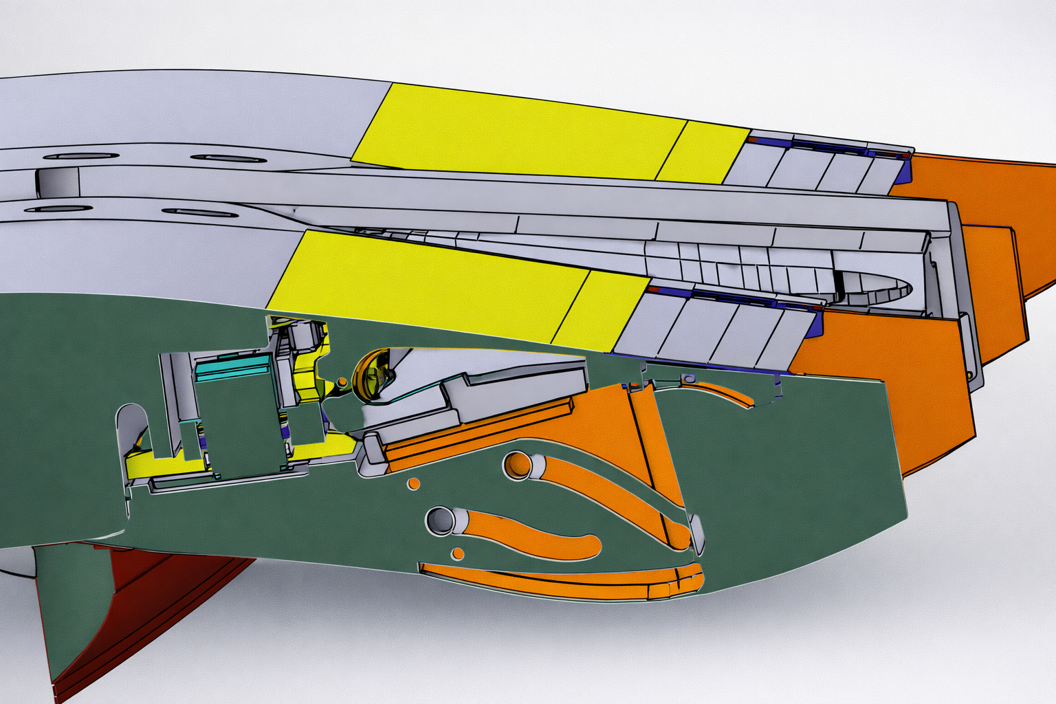
Detailed Design and CAD Engineering
Creation of a comprehensive CAD design, including manufacturing-oriented detailing, technical drawings, and complete production and assembly documentation.
Prototype and Demonstrator Development
Design and construction of demonstrators to validate the developed concepts. Findings from testing and experimental validation are systematically incorporated into engineering calculations and design refinement.
Final Design and System Integration
Finalization of the design in cooperation with project partners, ensuring full compliance with all functional, safety-related, and regulatory requirements.
What you get.
Results
native CAD, drawings, and BOMs
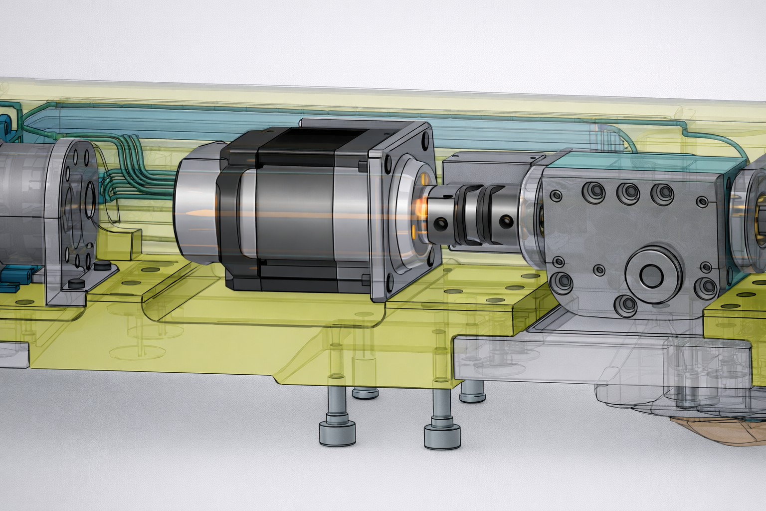
balance and sensor integration details
insert kits and quick modification options
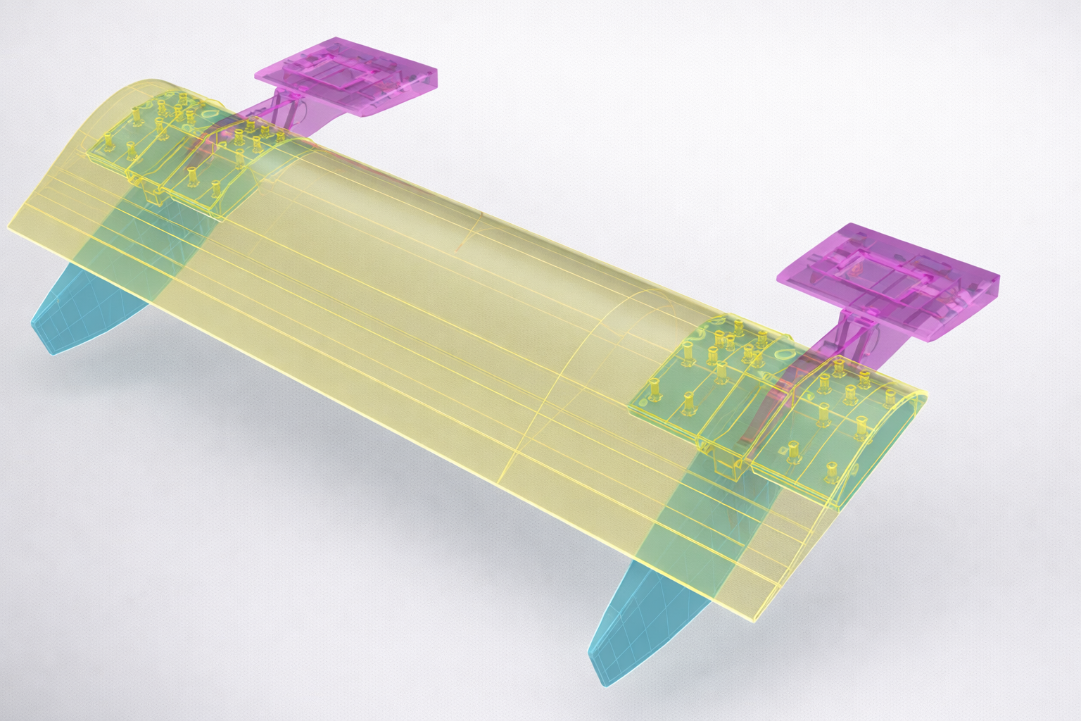
correlation geometry for CFD and FEM
Methods, Tools & Facilities
Methods
Master Geometry Models, CAD process standard, customer specific MGM rules, interference and tolerance control, automated CAD conversion, clash analysis, fast prototyping preparation
Tools
CATIA, Rhinoceros, Grasshopper, Datakit, Python CATIA interface, CAROLIN PLM, Rhino CAD converters, Interface Analyzer
Facilities
e.g. some Test Facility (PTF) at some University, some test rig with special capability